Quite a couple of Konami cores use the VLM5030 chip to generate human-like speech for in-game effects. While the replacement design created for the replay library does its job, it still falls behind the audio of an original chip. This is mainly due to the fact that the design was built based on MAME’s C model without detailed information of the chip’s (micro) architecture.
One of the obvious omissions is the random source that adds noise for unvoiced samples. It’s a TODO in the MAME driver and for the replacement design I went for an off-the-shelf LFSR, but it was a kludge from day 1.
Fortunately, the VLM5030 went through decapping and photographing at siliconpr0n in the past. Much of the analysis went into the MAME driver, except for the random source obviously. Thus I headed on to retrieve this bit from the design as well. Reading anything out of the die shot was hard in the beginning – the days when I worked on chip layouts are long gone and much is forgotten. As memory slowly came back, things went smoother day by day and I was able trace & capture some of the low hanging fruits for starters. E.g the central clock generation and some data path blocks.
Finding the random source was a bit like searching for the needle in a haystack since many counters and FSM state registers are actually implemented as LFSRs in the chip. Observing that LFSRs are very common in full-custom design style of that era was an interesting piece in the puzzle. Nowadays, such circuits are modeled with HDLs that automatically select implementation styles and state encodings. But using LFSRs instead of plain registers with a combinatorial fan-in cone keeps the gate count low. That’s especially nice if you have to design and layout each gate manually with little CAD support (I guess).
Long story short – probably the 4th or 5th LFSR turned out to be the one that generates randomness. It’s built from the cells inside the shaded area:
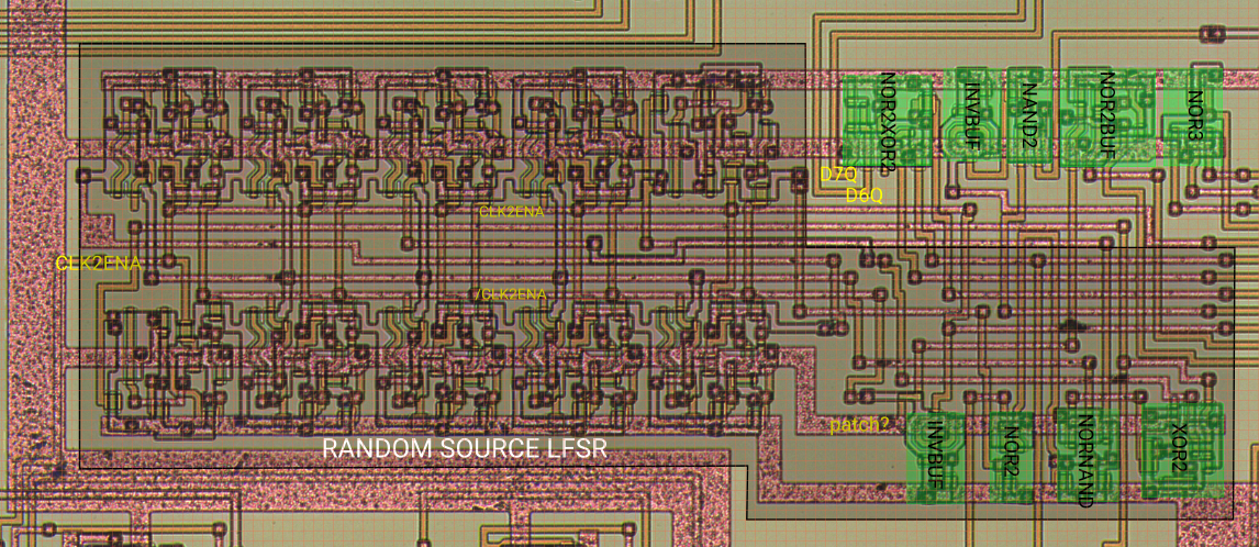
The 10 regular patterns on the left side are positive-edge-triggered D flip-flops forming the shift register chain. The 4 logic cells on the bottom right generate clock, reset and the feedback function.
Register 2 and 9 are tapped for the XOR and a 1 is forced in case all shift positions except 9 are 0:
    +->|0|-->|1|-->|2|-+>|3|-->|4|-->|5|-->|6|-->|7|-->|8|-->|9|-+-->  "random bit"
    |                  |                                         |
    |           /--|---+                                         |
    |   /--|---|XOR|                                             |
    +--|OR |    \--|---------------------------------------------+
        \--|--- "bits 0 to 8 are 0"

NOTE: Active RST shifts 0 into the LFSR.