Now with the extracted gate-level design in place, how does it perform?
The initial validation consisted of two basic phases:
- VHDL simulation in a test bench that dumps the PCM audio to a binary file. The binary is imported with Audacity and converted to WAV format for listening.
Goal: Prove that the design can actually generate correct samples in a flexible environment. - Integration of the gate-level design in several Konami FPGA conversions like Track’n’Field, Hypersports, Yie-Ar-Kung-Fu and others
Goal: Prove that the design interfaces correctly with the target systems and compare audio with real hardware.
Each method has its pros and cons. Simulation enables maximum controllability and observability of internal signals, but its execution speed is slow and variation of input is limited. Running the replacement in FPGA conversions adds variation in terms of system interfacing and sample/function coverage but offers almost zero control and observe features. One can just run the game and listen to the samples that are played in attract mode or in the first few levels.
To bridge both worlds, I created a test rig consisting of a small Cyclone II board that contains the gate-level replacement plus the ROM and also controls an external VLM5030 chip. It enables full control over the selection of speech samples without the need to trigger specific in-game situations.
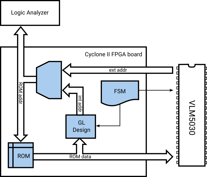
Block diagram of the VLM5030 test rig
Operation of the chip and the replacement is observed by a logic analyzer that’s hooked to the address bus. This makes use of VLM5030’s feature to output audio as 10 bit signed integer PCM samples on the address bus. Tracing both the chip’s and the replacement’s audio stream from a common trigger enables direct comparison of their PCM output with sample rate granularity.
The results are quite impressing – the screenshot below shows a range of Salamander’s “Destroy them all!” speech sample. Topmost channel is the gate-level design, followed by the chip and a re-run of the chip as the bottom channel. They’re perfectly in sync and sample values appear to match as well!
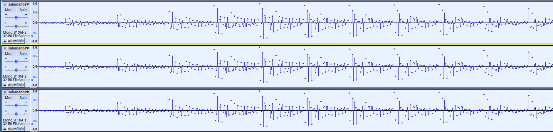
Detail of Salamander’s “Destroy them all!” at 20 ms. From top to bottom: GL design, VLM5030, VLM5030 2nd run
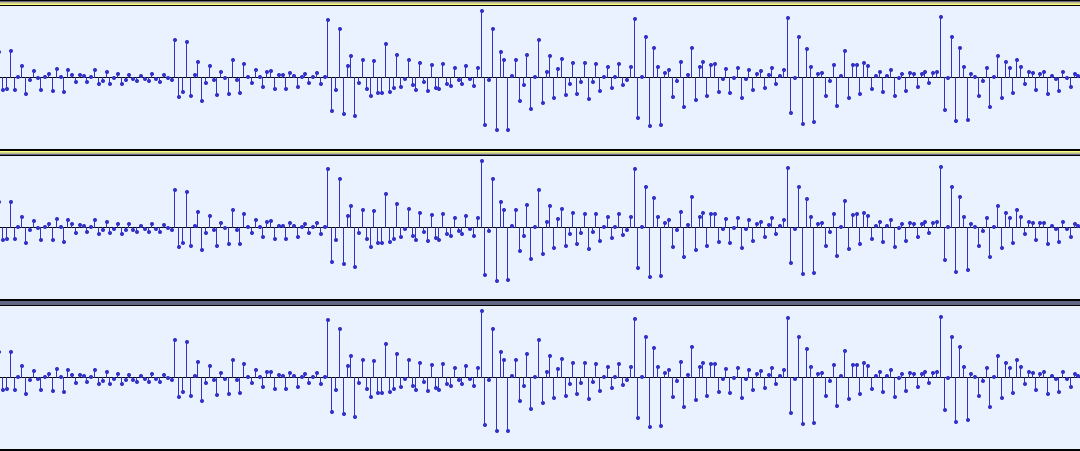
However, there are locations where all three waveforms begin to diverge (around the 0.108 s mark). It’s not necessarily just a difference between the gate-level design and the chip, but also the chip produces a different waveform during its 2nd run:
Detail of Salamander’s “Destroy them all!” at 100 ms. From top to bottom: GL design, VLM5030, VLM5030 2nd run
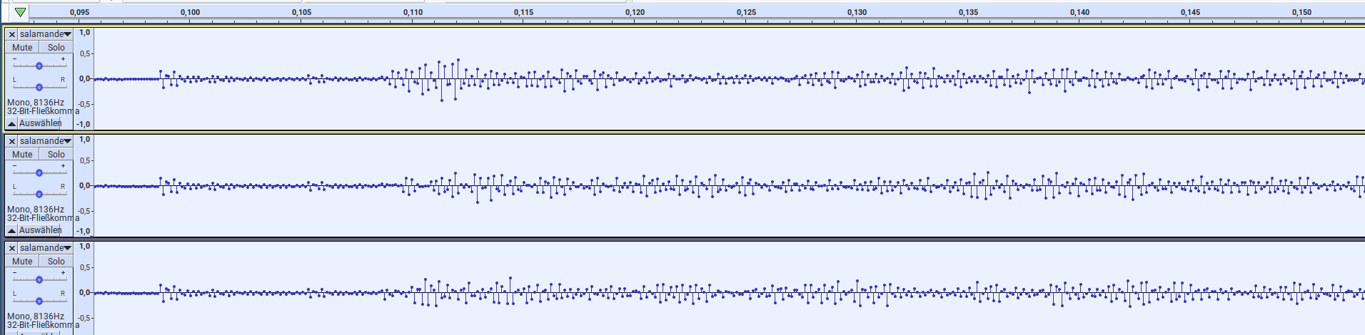
All three converge later at the 0.270 s mark and continue in lock-step:
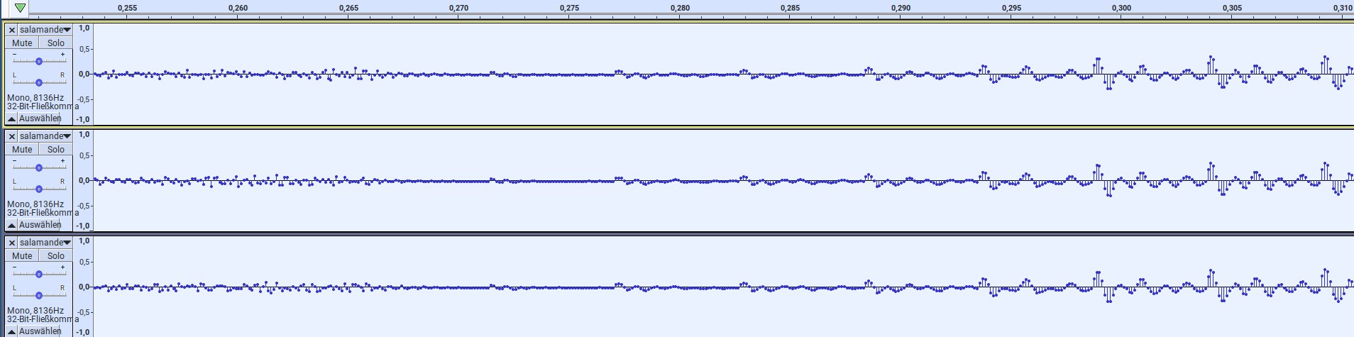
Detail of Salamander’s “Destroy them all!” at 255 ms. From top to bottom: GL design, VLM5030, VLM5030 2nd run
Conclusion
Initial comparison results show that the gate-level design produces identical audio waveforms for most of the frames. It differs during frames where the chip itself exhibits seemingly non-deterministic behaviour. In addition, the gate-level design also shows such behaviour and produces different waveforms during repeated runs of the same sample. Further analysis is required to understand this in more detail.
References
Gate-level replacement: salamander_gl.wav
VLM5030 chip: salamander_chip.wav
VLM5030 chip, 2nd run: salamander_chip_2ndrun.wav