
The previous post introduced a tracing procedure to extract logic gates from VLM5030’s layout information. This post shows how the procedure can be extended to extract VLM5030’s embedded ROMs.
Simple ROMs
The image below shows a portion of the sequencer ROM:
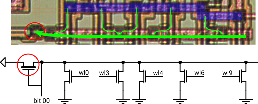
Bitline 0 in the sequencer ROM
- The blue metal bar is GND
- The horizontal red metal bar is bitline 0 (out of 37)
- The vertical orange polysilicon wires represent a total of 12 word lines
- The greenish overlays on polysilicon are 5 transistors that short the bitline to GND under control of the respective word line
Applying the tracing procedure extracts the function of bitline 0: It’s a NOR with 5 inputs.
To generalize the picture, we can conclude that each bitline is a NOR with 12 inputs. Each input is either 0 or 1, depending on the presence of a word line transistor:
- No word line transistor –> ‘0’
- Word line transistor present –> ‘1’
The other bitlines follow the same NOR concept, just with different combinations of word lines as inputs. Not too bad, this ROM is just a stacked pile of NORs.
Translated to VHDL:
-- 12 word lines
xwl <= na0 & a0 & a1 & na1 & na2 & a2 & a3 & na3 & na4 & a4 & xa5 & xa6;
-- bitlines as NOR of word lines with transistor pattern
xromdo <= (
  00 => norf(xwl, "100110100100"),
  01 => norf(xwl, "010110010100"),
  02 => norf(xwl, "011010011000"),
  ...
Array of ROM slices
Extracting the ROM that stores the K-factors is a bit more complex since it’s partitioned into 6 independent tables. Each of which connects to a common bus to output the data.
Shown below is bitline 0 exhibiting the same composition of word line transistors as before. There are two differences this time, though: The bitline is gated by 2 enable transistors (ena2 & ena0) and there’s no pull-up transistor for termination.
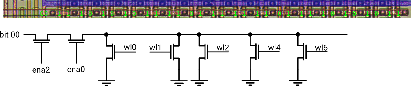
Bitline 0 in KROM table 2
Remember the statement about logic gates without termination? The job’s not done until we hit a pull-up – it ain’t over ’till the fat lady sings.
Tracing back further, we end up at a fat pull-up transistor that finally terminates all the bitlines 0 from each of the tables:
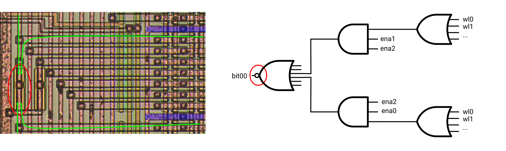 The corresponding logic function follows the hierarchical structure of the K-factor ROM:
- 10 NOR gates [9:0], generating the 10 bit output data vector (NOR[0] in the image above)
- Each NOR with up to 6 inputs, collecting the corresponding bitlines of the 6 tables (bitlines 0 of tables 2 and 3 in the image above)
- AND function, enabling the bitlines of the currently active table
- The bitlines themselves, represented by OR functions of the word lines where transistors are present
- AND function, enabling the bitlines of the currently active table
- Each NOR with up to 6 inputs, collecting the corresponding bitlines of the 6 tables (bitlines 0 of tables 2 and 3 in the image above)

Job done.