CRT Characterization and Emulation
I think many people agree that retro hardware looks best on CRTs from the same period. The downside is CRTs are expensive, bulky and hard to get hold of now.
I’ve got a small Sony PVM I use for testing, and a large Sony broadcast monitor that is most often used as a coffee table to be honest. Modern screens have a different gamut (colour space) but the gamut is generally larger than the Rec601 EBU spec for the CRT.
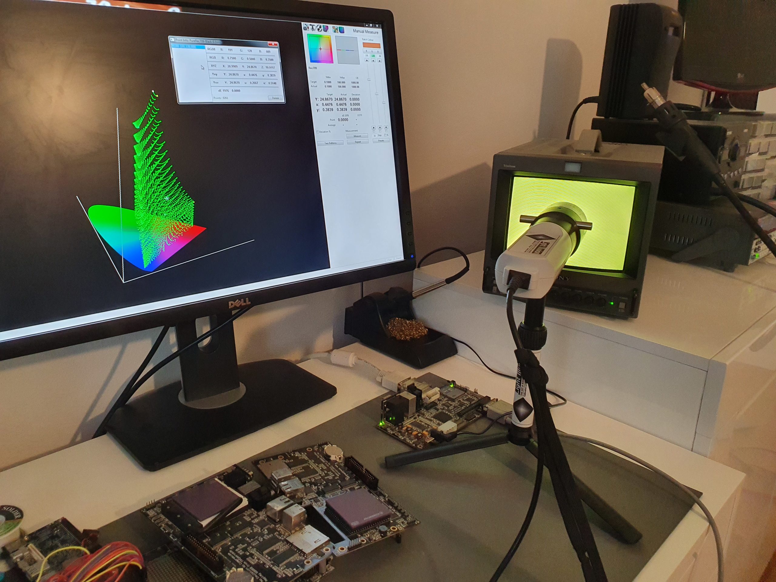
I’m lucky enough to have access to some software from Light Illusion and a high-end probe on loan. I’m using Replay1 as a patch generator controlled by the calibration software over a serial link. This wasn’t my initial plan, but it’s almost impossible to get PAL analog video out a modern PC. Replay1 has a reasonable quality analog output stage, filter and line driver – but it’s good to get any artefacts here included in the calibration.
I’m running an initial profile of the CRT at 80 nits, a little lower than usual, to stop any blooming. I’ll then run a profile of a standard LCD with default settings, probably one of my Dell panels. One of the really cool things about the ColourSpace software is give these two datasets, it can then generate a LUT (look up table) which will make the LCD look like the CRT. https://www.lightillusion.com/3d_lut_guide.html
I can then profile the LCD with the LUT applied by the tool, and see how far off from the CRT it is.
This data can then be built into the FPGA framework and be available to all cores. It’s likely a colour matrix and linear look up table will be sufficient, but I want to capture as much data as possible while I have the kit.
/MikeJ
Scramble video output analysis using Python and Spice
I wrote the first FPGA Scramble/Frogger core way back in 2007 (when we were all a lot younger)….

It’s been ported to all sorts of other hardware with little changes, but when we were moving it to our new build system I took the opportunity to look at the video output stage again. Looking at the schematics pics below, Scramble has a simple resistor DAC (top left) for the character video, additional outputs for stars (top right), a blue background for Frogger (bottom left) and logic for Missiles and Shells (bottom right).
The designers cleverly used the CS (chip select) pin of the output look up table (6331-1) to disable the outputs when the video level (VID1 & VID0) is zero. When the chip is not driving, the ends of the resistor are floating and don’t mess up any of the other outputs. However some things are on together, for example the missiles over characters. Also, some games have minor differences – Frogger has 470R on “blue”, but Scramble has a 390R resistor fitted.
I learnt a trick from Chris Brenner who wrote a script which ran through every combination of the Pacman audio DAC in SPICE, evaluated the output voltage and built a look up table for the FPGA. SPICE is an open source circuit simulator which has been around since the dawn of time. https://en.wikipedia.org/wiki/SPICE
I wrote a simple script in Python using PySpice, which builds the above circuit in every combination, modelling board output resistor and monitor termination. https://pyspice.fabrice-salvaire.fr/
If I picked datasheet typical values of 0.35 VoL (low output voltage) and 3.3 VoH (high output) we got the interesting result that the “off” black is slightly lower than the driven zero black. My guess is with the original CRT the black level was adjusted so all off was super-black and you couldn’t see the difference. It looked a bit odd on a modern display where the black level is fixed. I slightly simplified the drive and built a LUT (look up table) that accurately recreates the colours of the original game.
This is all in our new replay_arcade github repository which will go live shortly.
Happy retro gaming.
/MikeJ
# -*- coding: utf-8 -*-
"""
Created on Wed Aug 28 11:08:18 2019

@author: Mike
"""

import PySpice.Logging.Logging as Logging
logger = Logging.setup_logging()


from PySpice.Spice.Netlist import Circuit, SubCircuit, SubCircuitFactory
from PySpice.Unit import *

# VoH typ is 3.4V
# VoL typ is 0.35V
# chars     stars   "blue""    shell/missile
#
# 220R B    100 B   470R B*    100R R
# 470R B    150 B              100R G
# 220R G    100 G
# 470R G    150 G
#   1K G    100 R
# 220R R    150 R
# 470R R
#   1K R
# 470R to 0V

# blue is 390 on scramble
# blue is driven with tristate, alway '1'. Only when vid = 0

# stars are tristate but with 0/1 input
# stars are disabled when video is non black. Checked rom 0 = 0
# video dac is disabled for vid = 0

# missle/shell is also tri, can go on top of anything

# old monitors had higher input termination, 300-1K. We'll use 470R


# 470/390 2/3 blue_on shell_level shell_on stars_on vid_on level3

def sim(vid_level, vid_has_0, vid_on, stars_level, stars_on, shell_level, shell_on, blue_390_on, blue_470_on) :
    circuit = Circuit('DAC %u' % vid_level)

    circuit.V('_VH', 'in_vh', circuit.gnd, 3.3@u_V)
    circuit.V('_VL', 'in_vl', circuit.gnd, 0.25@u_V)

    ## video
    if (vid_on) :
        if (vid_level & 0x4) :
            circuit.R('_Vid2', 'in_vh', 'out', 220@u_Ω)
        else:
            circuit.R('_Vid2', 'in_vl', 'out', 220@u_Ω)

        if (vid_level & 0x2) :
            circuit.R('_Vid1', 'in_vh', 'out', 470@u_Ω)
        else:
            circuit.R('_Vid1', 'in_vl', 'out', 470@u_Ω)

        if (vid_has_0) :
            if (vid_level & 0x1) :
                circuit.R('_Vid0', 'in_vh', 'out',   1@u_kΩ)
            else:
                circuit.R('_Vid0', 'in_vl', 'out',   1@u_kΩ)

    ##  stars
    if (stars_on) :
        if (stars_level & 0x2) :
            circuit.R('_Star1', 'in_vh', 'out', 100@u_Ω)
        else:
            circuit.R('_Star1', 'in_vl', 'out', 100@u_Ω)

        if (stars_level & 0x1) :
            circuit.R('_Star0', 'in_vh', 'out', 150@u_Ω)
        else:
            circuit.R('_Star0', 'in_vl', 'out', 150@u_Ω)

    ## shell
    if (shell_on):
        if (shell_level & 0x1) :
            circuit.R('_Shell0', 'in_vh', 'out', 100@u_Ω)
        else:
            circuit.R('_Shell0', 'in_vl', 'out', 100@u_Ω)

    ## "blue"
    if (blue_390_on):
        circuit.R('_Blue390', 'in_vh', 'out', 390@u_Ω)

    if (blue_470_on):
        circuit.R('_Blue470', 'in_vh', 'out', 470@u_Ω)

    # board output res to gnd
    circuit.R('_Load', 'out', circuit.gnd, 470@u_Ω)

    # term
    circuit.R('_TERM', 'out', circuit.gnd, 470@u_Ω)

    #print(circuit)

    simulator = circuit.simulator(temperature=25, nominal_temperature=25)
    analysis = simulator.operating_point()

    for node in analysis.nodes.values():
        if (str(node) == 'out'):
            #print('{}'.format(float(node)))
            return float(node)


# Lowest level is with missile/shell/stars disabled
# note, the DAC essentially has two black levels
# if vid=0 the dac is off, so super black
# vid = 1/2/3 but one colour chanel from the prom could =0, so dac black > "off" black

min_val  = sim(0, True, False, 0,False , 0, False, False, False)
print('min rg:',min_val)

# max shell on plus stars plus blue
max_val  =  sim(7, True, False, 3,True , 1, True, True, False)
print('max rg:',max_val)

# 2 chan dac (blue) i've added a slight gain so the white point matches the 3 chan
#dac2_gain = 1.056  # ideal
dac2_gain = 1.04


# dac3bit shell_ena shell_level  level
#       5        4           3    2..0


# blue_470 blue_ena shell_ena shell_level star_ena level
#        6        5         4          3         2  1..0

f = open('scramble_lut_vid.hex', 'w')
print('vid on')

for i in range (0,64):
    dac3bit     = bool(i & 0x20)
    shell_ena   = bool(i & 0x10)
    shell_level = bool(i & 0x08)
    vid_level   = i & 0x7

    #print('{} {} {} {}'.format(dac3bit,shell_ena, shell_level, vid_level))
    val = sim(vid_level, dac3bit, True, 0, False, shell_level, shell_ena , False, False)
    lut = (val- min_val) / (max_val - min_val)
    if (not dac3bit):
        lut *= dac2_gain
    lut_int = int(round(lut * 255))
    print('level {:7b}, {:f} {}'.format(i, val,lut_int))
    line = ('{:02X} \n'.format(lut_int))
    f.write(line)

f.close()


f = open('scramble_lut_nvid.hex', 'w')
print('vid off')

for i in range (0,128):
    blue_470_on = bool(i & 0x20) and     bool(i & 0x40)
    blue_390_on = bool(i & 0x20) and not bool(i & 0x40)

    shell_ena   = bool(i & 0x10)
    shell_level = bool(i & 0x08)
    star_ena    = bool(i & 0x04)
    star_level  = i & 0x3

    #print('{} {} {} {} {} {} {}'.format(i, blue_470_on,blue_390_on, shell_ena, shell_level, star_ena, star_level))

    val = sim(0, False, False, star_level, star_ena, shell_level, shell_ena , blue_390_on, blue_470_on)
    lut = (val- min_val) / (max_val - min_val)
    if (not dac3bit):
        lut *= dac2_gain
    lut_int = int(round(lut * 255))
    print('level {:7b}, {:f} {}'.format(i, val,lut_int))
    line = ('{:02X} \n'.format(lut_int))
    f.write(line)

f.close()
Gearing up for Replay2 Production
Replay2 is still in layout and a few things are awaiting design closure (primarily memory configuration). The FPGA chosen is a Xilinx Ultrascale+ device (super fast) with Quad core A-53s, dual R5s and a Maii GPU.
The CPU section has DDR4 DRAM, and the FPGA most likely 2 x DDR3 memories. The board has a display port output for the CPU side, DVI/HDMI as well as a high quality DAC for analog output and the JAMMA adapter.
I hope to get some more details posted soon. I’ve started to order parts for the prototype and this morning visited a local SMD prototyping house to see if they could build it.
The production boards will most likely be massed produced by a well known hobby hardware manufacturer, but it’s handy to get a few boards quickly done for initial debug (and smoke test).
MikeJ
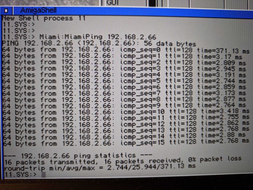
68060 Ethernet and SD card support
Our resident coding genius Erique has been hard at work finishing off driver support for the DB. Source and the ROM binary can be round here : https://github.com/FPGAArcade/amiga_code
Please also take a look at the FAQ here:
The Ethernet (unlike some other solutions) relies on a 16 bit parallel interface MAC which sits on the ‘060 local bus. There is scope for improving performance, but first I want to increase the CPU frequency as high as possible. Many rev6 060s will work at 113MHz.There is a jumper on board to increase the core voltage by ~5% if necessary via the dedicated DC/DC driving the CPU.
Another question I’ve been asked… We have 128MB of directly connected SDRAM, why not use DDR2/3, surely that’s “faster”. No. The SDRAM can burst read/write 4 words at the maximum speed the CPU can, so there is no performance gain by using a higher frequency (unless you want to share the memory with another controller – but we have the main board DDR memory for that). The real killer is read latency. If we put an FPGA bridge in the path, the reads would have to pass through the FPGA controller to the memory and back again. Admittedly the 060 on die cache solves this problem for many cases, but not all. For R2 we will have very high speed memories on the main board, but I think I will still add an option for local SDRAM for this reason.
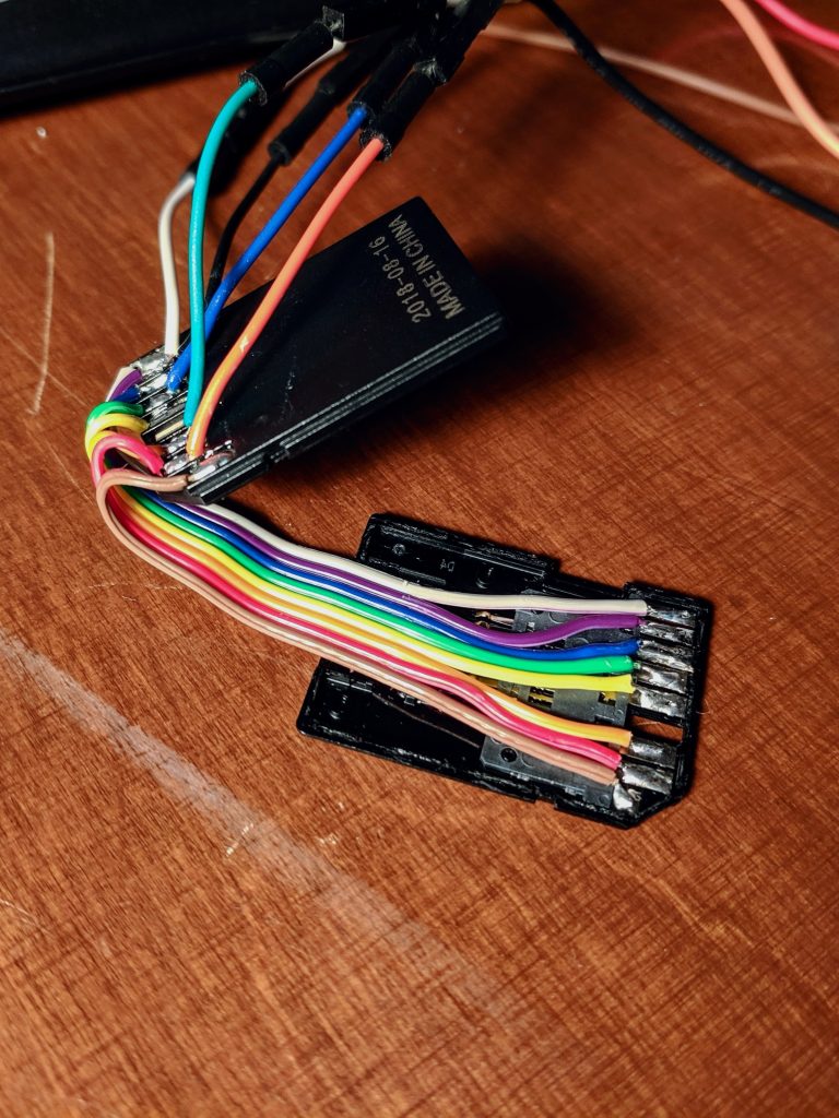
The picture below shows Erique’s homebrew SD card adapter. This allows him to connect a logic analyzer while connected to the SD card …. and the board being in it’s case. Neat!