ROM extraction
The previous post introduced a tracing procedure to extract logic gates from VLM5030’s layout information. This post shows how the procedure can be extended to extract VLM5030’s embedded ROMs.
Simple ROMs
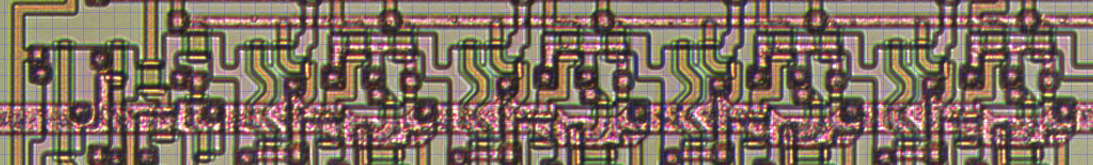
The image below shows a portion of the sequencer ROM:
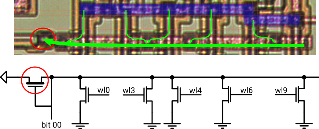
Bitline 0 in the sequencer ROM
- The blue metal bar is GND
- The horizontal red metal bar is bitline 0 (out of 37)
- The vertical orange polysilicon wires represent a total of 12 word lines
- The greenish overlays on polysilicon are 5 transistors that short the bitline to GND under control of the respective word line
Applying the tracing procedure extracts the function of bitline 0: It’s a NOR with 5 inputs.
To generalize the picture, we can conclude that each bitline is a NOR with 12 inputs. Each input is either 0 or 1, depending on the presence of a word line transistor:
- No word line transistor –> ‘0’
- Word line transistor present –> ‘1’
The other bitlines follow the same NOR concept, just with different combinations of word lines as inputs. Not too bad, this ROM is just a stacked pile of NORs.
Translated to VHDL:
-- 12 word lines
xwl <= na0 & a0 & a1 & na1 & na2 & a2 & a3 & na3 & na4 & a4 & xa5 & xa6;
-- bitlines as NOR of word lines with transistor pattern
xromdo <= (
  00 => norf(xwl, "100110100100"),
  01 => norf(xwl, "010110010100"),
  02 => norf(xwl, "011010011000"),
  ...
Array of ROM slices
Extracting the ROM that stores the K-factors is a bit more complex since it’s partitioned into 6 independent tables. Each of which connects to a common bus to output the data.
Shown below is bitline 0 exhibiting the same composition of word line transistors as before. There are two differences this time, though: The bitline is gated by 2 enable transistors (ena2 & ena0) and there’s no pull-up transistor for termination.
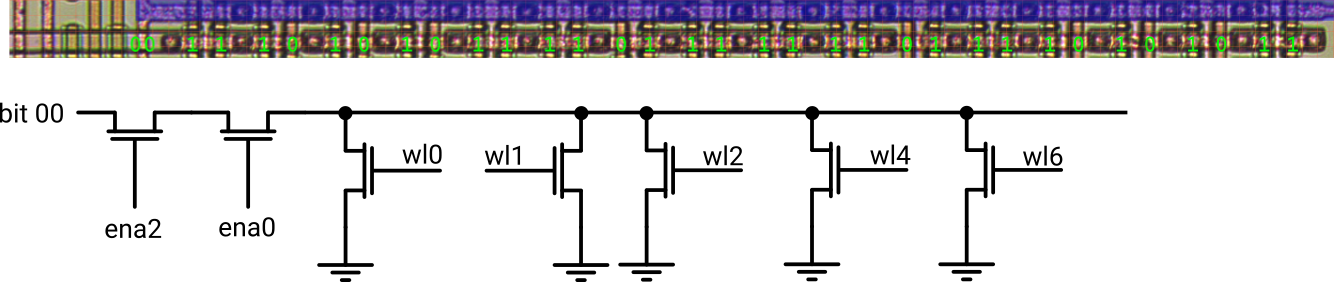
Bitline 0 in KROM table 2
Remember the statement about logic gates without termination? The job’s not done until we hit a pull-up – it ain’t over ’till the fat lady sings.
Tracing back further, we end up at a fat pull-up transistor that finally terminates all the bitlines 0 from each of the tables:
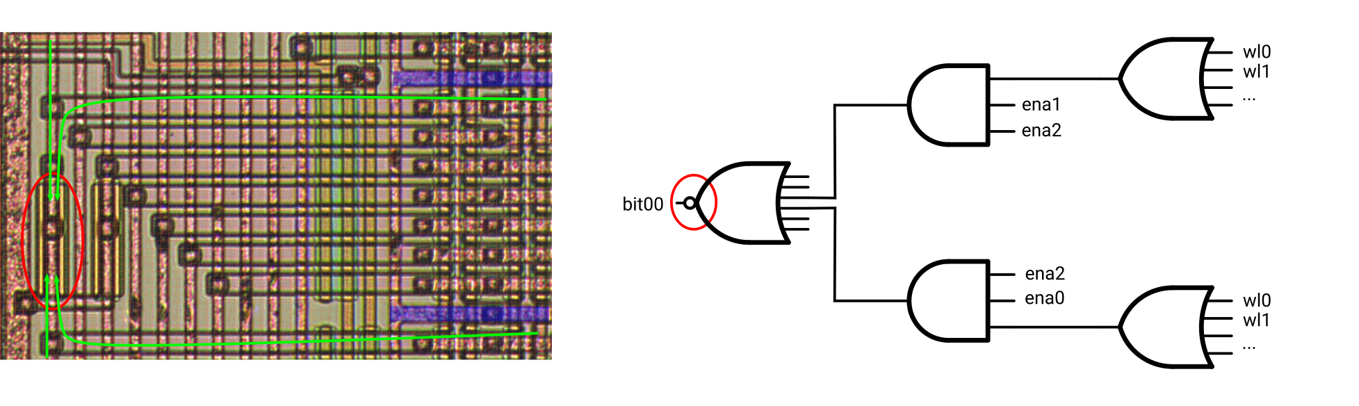 The corresponding logic function follows the hierarchical structure of the K-factor ROM:
- 10 NOR gates [9:0], generating the 10 bit output data vector (NOR[0] in the image above)
- Each NOR with up to 6 inputs, collecting the corresponding bitlines of the 6 tables (bitlines 0 of tables 2 and 3 in the image above)
- AND function, enabling the bitlines of the currently active table
- The bitlines themselves, represented by OR functions of the word lines where transistors are present
- AND function, enabling the bitlines of the currently active table
- Each NOR with up to 6 inputs, collecting the corresponding bitlines of the 6 tables (bitlines 0 of tables 2 and 3 in the image above)

Job done.
Logic gates extraction
The technology
We need to set the stage first for this post. The VLM5030 is built from depletion-load NMOS logic. This means there are basically two types of devices:
- Enhancement-mode NMOS transistors for shorting a node to GND (or forwarding voltage between two nodes)
- Depletion-mode NMOS transistors to act as pull-ups to VDD
In addition, there are a total of three layers to connect devices in decreasing order or conductivity:
- Metal (red) for general signal routing and VDD & GND distribution
- Polysilicon (orange) for general signal routing and transistor gates
- Diffusion (transparent) for routing over small distances or of uncritical signals
Layers are interconnected with vias:
- Metal to polysilicon
- Metal to diffusion
A remarkable item is that the VLM5030 doesn’t connect polysilicon directly to diffusion. Consequently, whenever a signal needs to change from polysilicon to diffusion or vice versa, there’s first a via from polysilicon to metal and next to it a second via connecting metal to diffusion. Other chips like the MOS6502 solve this with buried contacts that allow direct connections between polysilicon and diffusion. So Sanyo used a less advanced technology, probably to save on cost per wafer. But it actually helps the tracing task since the layer change is pretty obvious this way.
Basic logic gates
To understand which kind of logic gate is built by a particular group of transistors, apply the following basic tracing procedure:
- Start from the GND metal
- Follow the path(s) along the enhancement-mode transistors
- Stop at the pull-up transistor
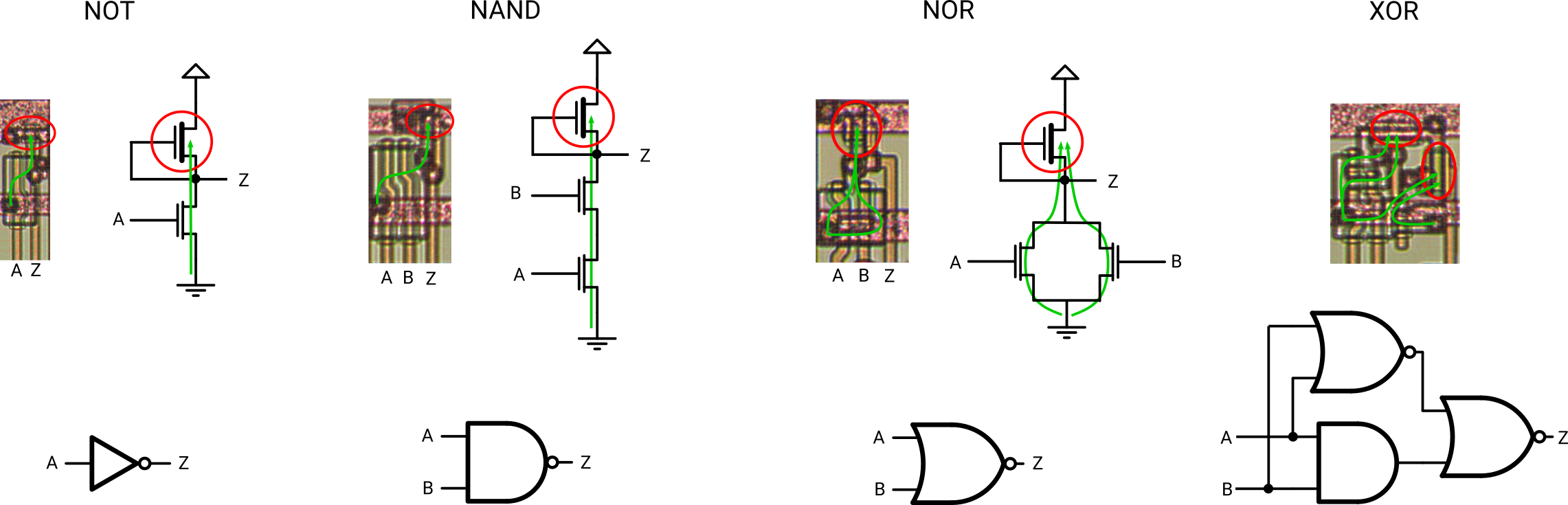
Tracing procedure applied to basic logic gates
The pull-up transistor acts as termination, so there must always exist one in a gate; not zero, not two, exactly one. It corresponds to the gate’s dot.
This aspect is important for tracing – the logic gate is incomplete without a pull-up.
Randomness on a microscopic level
Quite a couple of Konami cores use the VLM5030 chip to generate human-like speech for in-game effects. While the replacement design created for the replay library does its job, it still falls behind the audio of an original chip. This is mainly due to the fact that the design was built based on MAME’s C model without detailed information of the chip’s (micro) architecture.
One of the obvious omissions is the random source that adds noise for unvoiced samples. It’s a TODO in the MAME driver and for the replacement design I went for an off-the-shelf LFSR, but it was a kludge from day 1.
Fortunately, the VLM5030 went through decapping and photographing at siliconpr0n in the past. Much of the analysis went into the MAME driver, except for the random source obviously. Thus I headed on to retrieve this bit from the design as well. Reading anything out of the die shot was hard in the beginning – the days when I worked on chip layouts are long gone and much is forgotten. As memory slowly came back, things went smoother day by day and I was able trace & capture some of the low hanging fruits for starters. E.g the central clock generation and some data path blocks.
Finding the random source was a bit like searching for the needle in a haystack since many counters and FSM state registers are actually implemented as LFSRs in the chip. Observing that LFSRs are very common in full-custom design style of that era was an interesting piece in the puzzle. Nowadays, such circuits are modeled with HDLs that automatically select implementation styles and state encodings. But using LFSRs instead of plain registers with a combinatorial fan-in cone keeps the gate count low. That’s especially nice if you have to design and layout each gate manually with little CAD support (I guess).
Long story short – probably the 4th or 5th LFSR turned out to be the one that generates randomness. It’s built from the cells inside the shaded area:
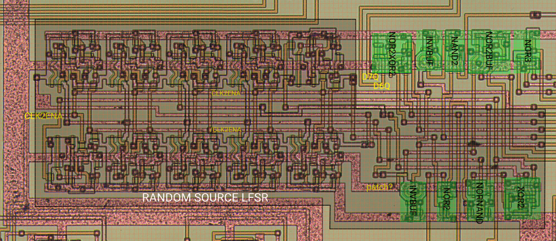
The 10 regular patterns on the left side are positive-edge-triggered D flip-flops forming the shift register chain. The 4 logic cells on the bottom right generate clock, reset and the feedback function.
Register 2 and 9 are tapped for the XOR and a 1 is forced in case all shift positions except 9 are 0:
    +->|0|-->|1|-->|2|-+>|3|-->|4|-->|5|-->|6|-->|7|-->|8|-->|9|-+-->  "random bit"
    |                  |                                         |
    |           /--|---+                                         |
    |   /--|---|XOR|                                             |
    +--|OR |    \--|---------------------------------------------+
        \--|--- "bits 0 to 8 are 0"

NOTE: Active RST shifts 0 into the LFSR.
It’s-a me, Mario!

Nintendo Entertainment System – Evan Amos
There has been quite a lot of work going on in the background with the FPGA Arcade project, not the least of which is a host of new core releases.
As you may have guessed from the image, the NES is now available for the Replay and MKR Vidor4000 platforms. This version of the NES core includes a transistor net-list based 6502 by Andrew Holme.
For FPGA capacity reasons, the Vidor4000 release of the NES has been split into 3 separate cores by mapper: MMC, VRC and Others, with PAL and NTSC versions for each. R1 users can enjoy all the mappers in a single core.
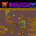
There’s also been a number of new Arcade cores released including Track&Field and its sequel Hypersports; Tutankham, Time Pilot, Donkey Kong and more…
-
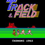
- Track & Field
-

- Donkey Kong
-

- Yie Ar Kung-Fu
-
- Tutankham
-

- Time Pilot
-

- Roc’n Rope
Further information can be found in the FAQ section. All the latest stable core releases for supported platforms are available for download from the releases site and if you’re the adventurous sort, continuous development builds via the CI build server.
There’s also a number of further exciting developments to share, but that’s for a future post.